


24 Month maintenance

Fast delivery

24 Hour treatment
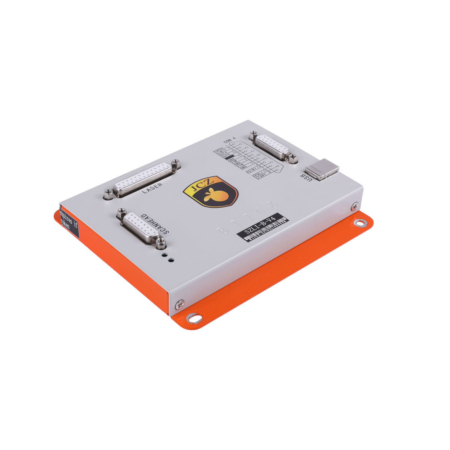
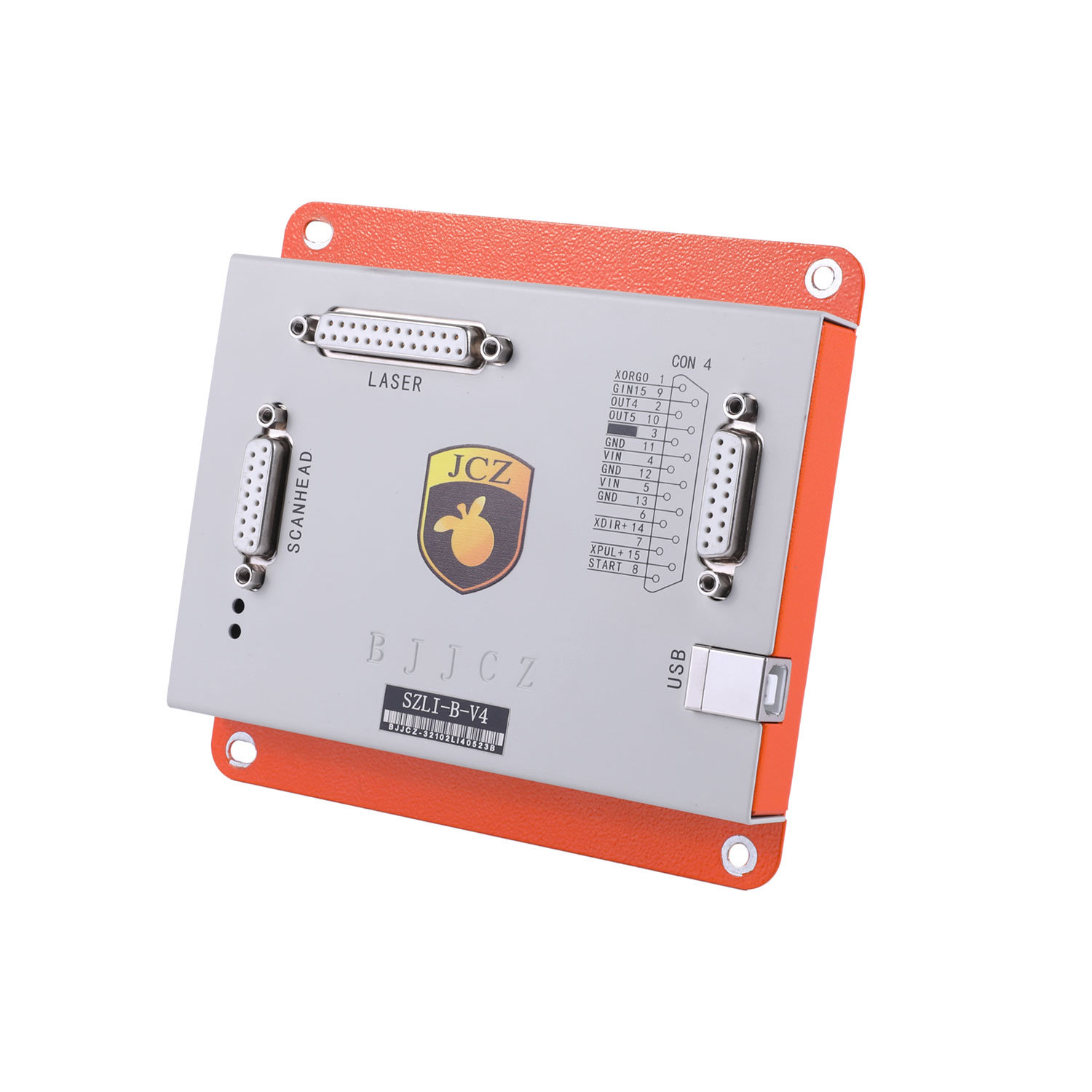
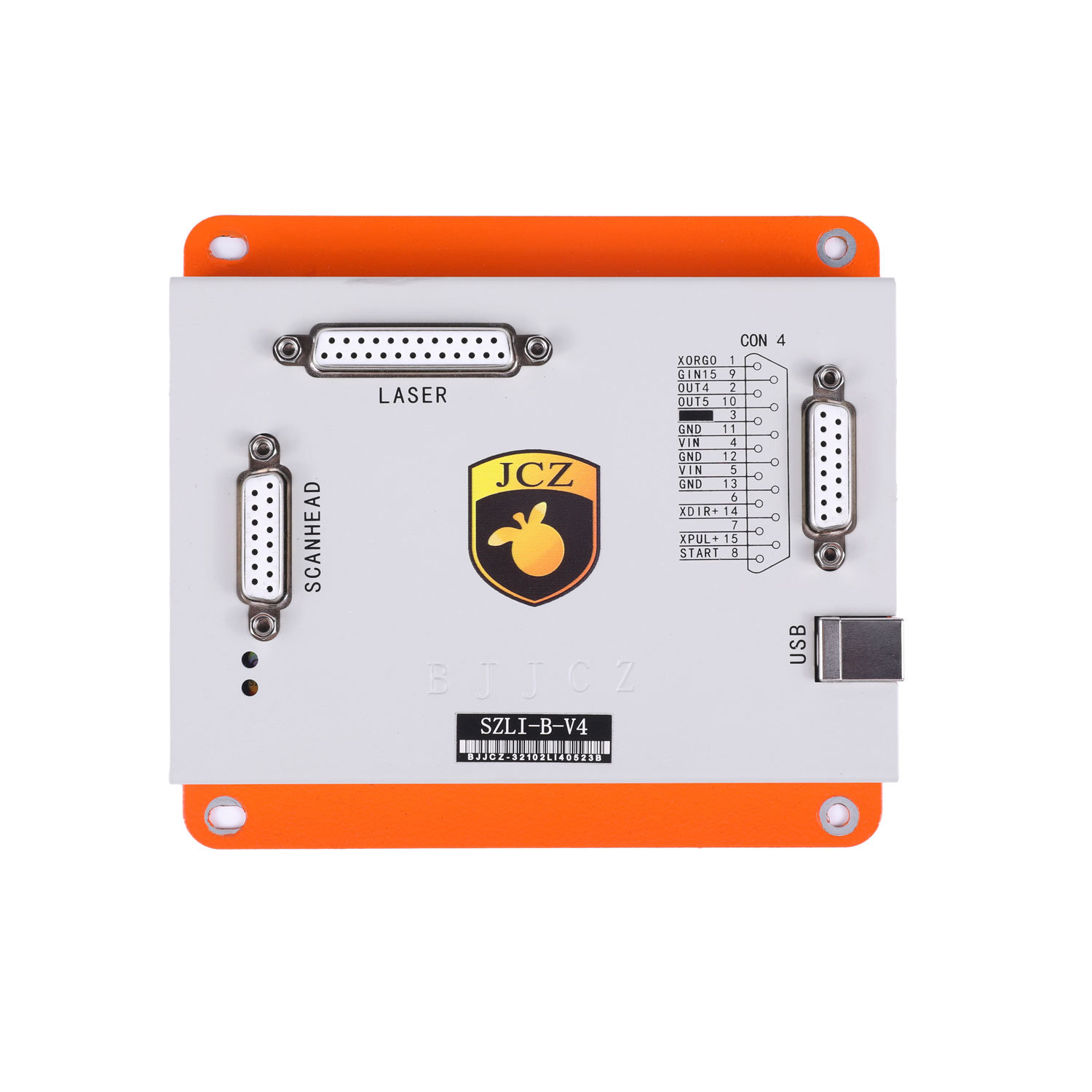
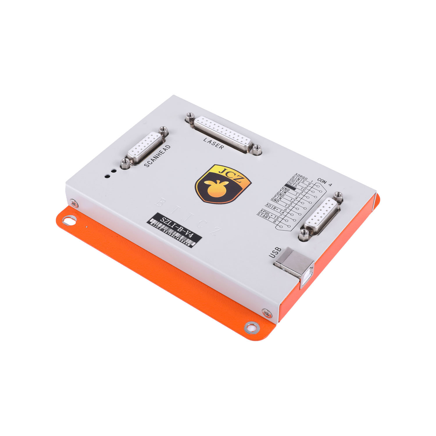
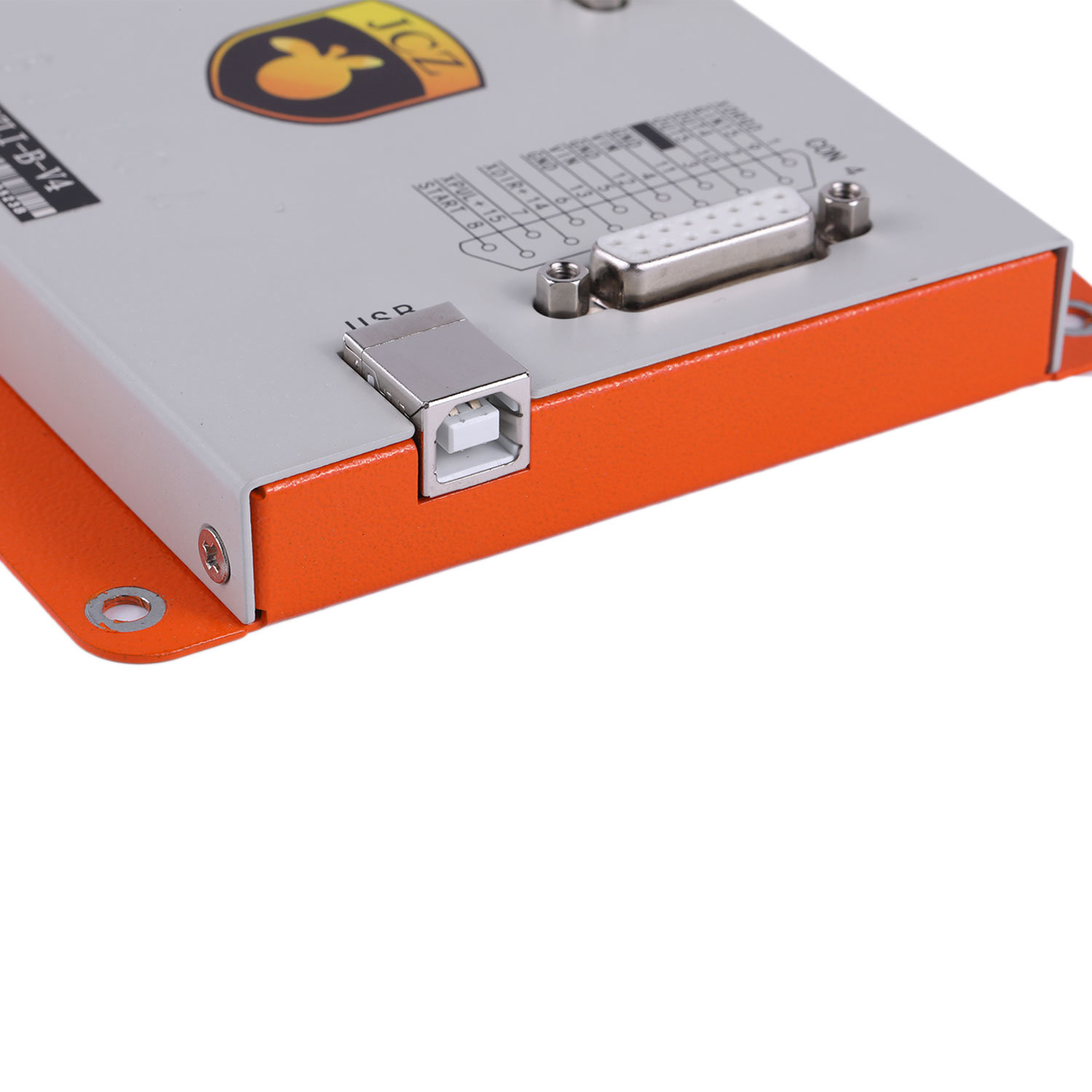
Model: EZCAD2 Control Card (e.g., LMCV4, LMCV5, etc.)
Compatibility: Works with EZCAD2 software for laser marking systems.
Supported Laser Types: Fiber, CO2, UV, and green lasers.
Applications: Laser marking, engraving, cutting, and etching on various materials (metals, plastics, ceramics, etc.).
High-Speed Processing: Enables fast marking speeds.
Precision Control: Supports high-resolution marking.
Versatility: Compatible with 2D and 3D marking.
User-Friendly Interface: Integrates seamlessly with EZCAD2 software.
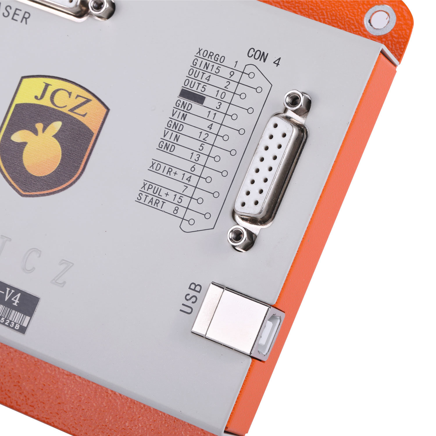
Multiple I/O Ports: For connectivity with external devices (e.g., footswitch, rotary axis, etc.).
Input Voltage: Typically 24V DC (check specific model for exact requirements).
Communication Interface: USB, Ethernet, or RS232.
Control Signals: TTL, analog, or PWM for laser control.
Dimensions: Varies by model (e.g., 150mm x 100mm x 25mm).
Operating Temperature: 0°C to 40°C (32°F to 104°F).
Storage Temperature: -20°C to 60°C (-4°F to 140°F).
Humidity: 10% to 90% (non-condensing).
| Pin Number | Function | Description |
|---|---|---|
| 1 | GND | Ground connection |
| 2 | +24V | Power supply input (24V DC) |
| 3 | LASER ON/OFF | TTL signal to control laser firing |
| 4 | PWM Signal | Pulse Width Modulation for laser power |
| 5 | Emergency Stop | Emergency stop input |
| 6 | Footswitch Input | External footswitch for manual control |
| 7 | Rotary Axis Signal | Control signal for rotary axis attachment |
| 8 | Analog Signal | Analog control for laser power adjustment |
Power Off: Ensure the laser system is powered off before installation.
Mounting: Securely mount the control card in the designated slot or enclosure.
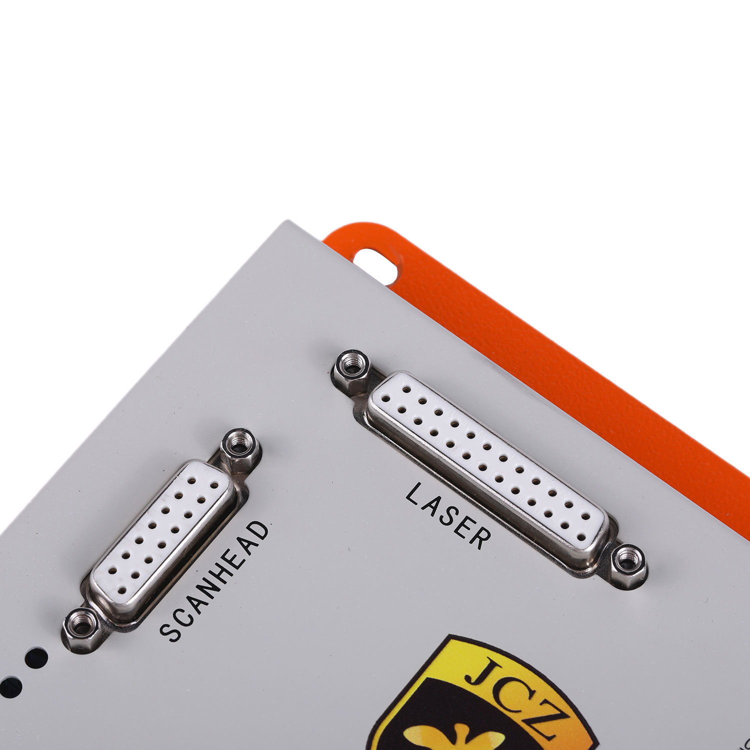
Connections:
Connect the power supply (24V DC) to the appropriate pins.
Connect the laser source to the control card using the provided cables.
Attach external devices (e.g., footswitch, rotary axis) to the corresponding ports.
Software Setup:
Install the EZCAD2 software on the connected PC.
Configure the software to recognize the control card and laser source.
Test Run: Perform a test run to ensure proper functionality.
| Issue | Possible Cause | Solution |
|---|---|---|
| No laser output | Incorrect wiring or power supply | Check connections and power supply |
| Poor marking quality | Incorrect focus or laser settings | Adjust focus and laser parameters |
| Control card not detected | Faulty USB/Ethernet connection | Reconnect or replace the cable |
| Overheating | Poor ventilation or high ambient | Ensure proper cooling and airflow |
| Error messages in software | Software or driver issues | Reinstall EZCAD2 software and drivers |
Regularly clean the control card and connections to prevent dust buildup.
Ensure proper ventilation to avoid overheating.
Periodically check and tighten all connections.
Keep the EZCAD2 software updated to the latest version.
Always disconnect power before servicing the control card.
Avoid exposing the card to moisture or extreme temperatures.
Use anti-static precautions when handling the card to prevent damage.
 Click this WhatsApp icon to contact us!


Copyright © Shenzhen Lei Kang Machinery Equipment Co.,Ltd Privacy Policy


About Us

Products
Application
Supports
 +86-15797743424

 English
